Business Process and Functional Modeling
Business Process and Functional Modeling transforms requirements into logical models that describe how a business system interacts with its environment. These models are implementation-independent, meaning they focus on what the system does rather than how it does it.
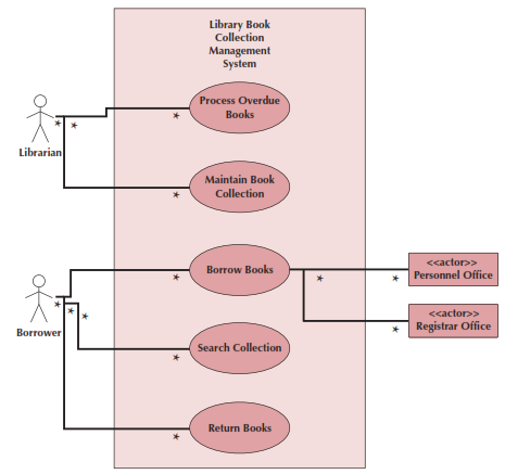
Use Case Diagrams
Use case diagrams illustrate how a system interacts with its environment through discrete activities.
The main elements include:
- Actors
- Users or other systems that interact with the system
- Represented by stick figures
- Use Cases
- Major processes that provide benefits to users
- Represented by ovals and named with verb phrases
- Relationships
- Association
Basic interaction between actor and use case - Include
One use case includes functionality of another - Extend
Optional behavior extension - Generalization
Specialized version of another use case
- Association
- Subject Boundary
- Named box showing system scope
- Contains all use cases
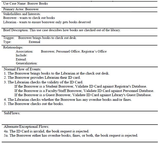
Use Case Descriptions
- Overview Section
- Name
- Primary actor
- Brief description
- Stakeholders
- Triggers
- Relationships Section
- Association relationships
- Include relationships
- Extend relationships
- Generalization relationships
- Flow of Events
- Normal Flow: Main success scenario
- Sub-flows: Decomposed normal flows
- Alternate/Exceptional Flows: Alternative scenarios
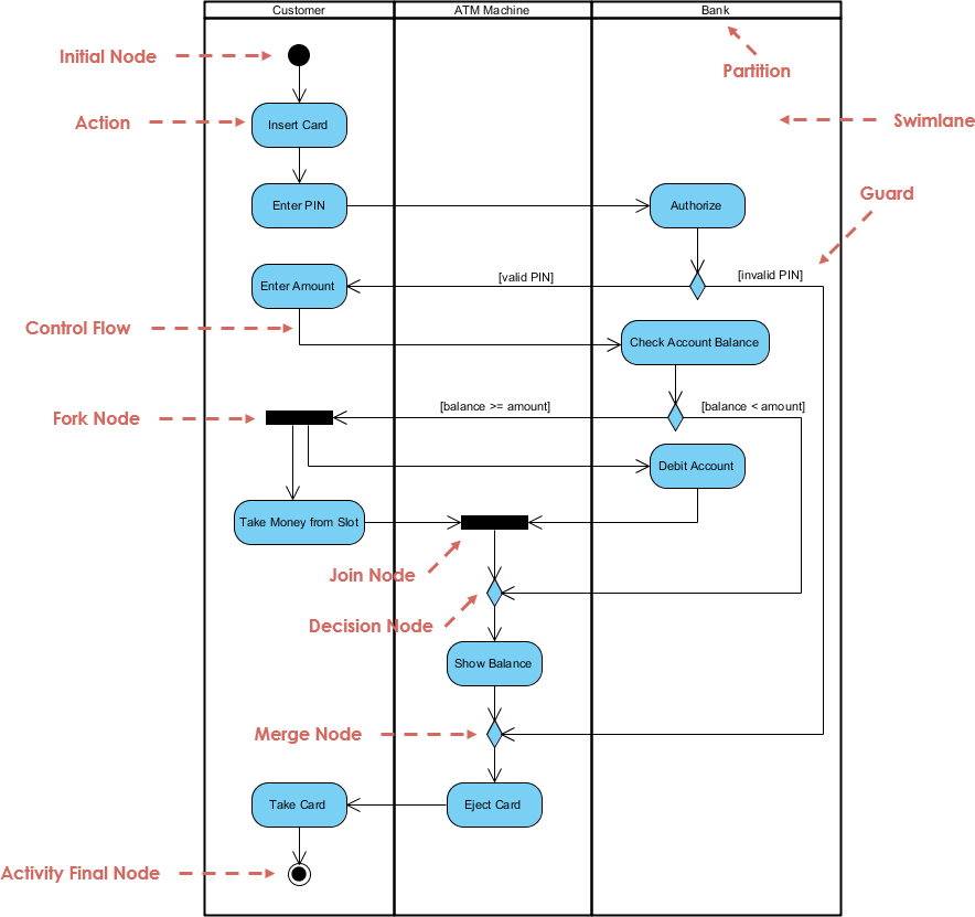
Activity Diagrams
Activity diagrams show the sequence of activities in a business process, independent of objects.